
New tech tip 3-24
ZW 250/275 fix for loosing power to track when whistle control is pushed all the way forward.
We refurbish hundreds of these transformers, and have noticed occasionally an issue where when you push the whistle control all the way forward it may remove the power to the center rail. Most folks figure that out and just don’t push it that far. What we have discovered is that his issue is caused by the spring that keeps the whistle/direction control lever centered. With years of use the straight portion of the spring gets bent. Tried our best to restraighten without success. Sometimes we were able to adjust the switch contacts, and sometimes not to fix the problem. It is our nature not to let something like this slide by and have spent countless hours trying to figure out a way to solve this problem.
TA-DAAA, figured it out! When you go through the solution we came up with you will probably ask yourself, simple enough, why did it take so many years to figure out? No answer to this question. Anyway, here ya go. The fix is so simple almost anyone can do the fix in les then 5 minutes, and here it is:
Materials needed:
Get some 18 gauge stranded wire (if you can’t find it let me know and I will mail you a chunk). Strip off the outside shielding about 3” or so. The shielding is what you are going to use, not the wire.
Cut the 3” piece of shielding in ½
A dab of thick glue, Gorilla Glue or super glue Gel (do not use any liquid glue) or a dab of hot glue. (this is optional)
DA Procedure:
- Remove all the wires off the transformer.
- Unplug the transformer.
- Remove the top 4 screws on the top of the transformer cover.
- Remove the red and green bulb covers. Sometimes you must bend the light sockets when installing the cover to make the cover seat properly.
- Turn the transformer so the back of the transformer is facing you.
- Look at the whistle control spring that is used to bring the control back to center.
- Push the whistle control towards you and observe the slot that the spring lever slides into.
- The problem is that there is a slight space between the spring lever and the stop in the fiber housing.
- What you are going to do is put the insulation from the wire between the spring lever and the end of slot.
- Take a small flat bladed screwdriver and push the insulation to the end of the slot.
- Allow not more then ½” inch of the insulation thru the slot and leave about the same on the side you where you put thru the insulation.
- Operate the whistle control a few times and you can see what the idea is.
- When we do this, we add a dab of glue to the outside of the insulator to the fiber housing, just in case of shipping it may get jostled out, in your case probably not necessary.
Once completed you will notice that the lever does not throw quite as far as it did. For this reason, suggest you do both sides so they will be equal. Again BE SUPER CAREFUL if you elect to use glue, DO NOT ALLOW ANY GLUE TO GO ON THE OTHE SIDE OF THE FIBER OR DRIP DOWN UNTO THE BEARINGS!! Again, the glue is probably not necessary for you.
This is the spring that is discussed, note is bent.
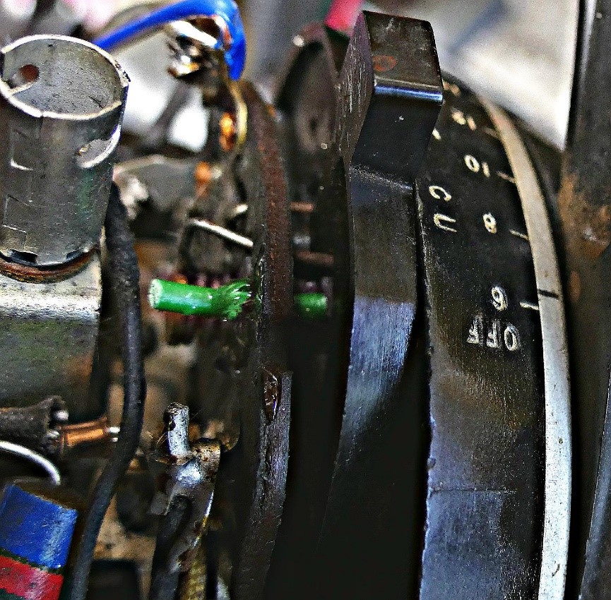
This is the piece of insulator installed.
Here at Tinman, we will be making these installations to every ZW transformer we refurbish, that has the power off issue. If you have this issue with your transformer, you purchased, or had refurbished from us and don’t feel comfortable doing the modification, no worries. Send your transformer back to us and we will install the modification free of charge and pay the shipping back to you, and yes, we do realize it could be in the hundreds.
How to Select a Transformer
Buying a transformer can mean making a significant investment for a train hobbyist. Deciding which transformer to buy can be very confusing. To help you we have listed some ideas to consider.
Below are some points to consider before making a buy decision.
First, don’t decide on what your current needs are. Think about what your ultimate layout will be. Below are some thoughts that may help.
Number of trains you foresee you would like to operate at any one time:
- Transformers are designed to be able to normally run anywhere from one to four trains at one time, sorta. For example, the most popular transformer ever made was Lionel’s ZW. It is advertised as being able to run 4 trains. They will do that, but only 2 of the 4 outputs have whistle and reversing switches. If you want to operate 4 trains and two of them may be a trolley or a bumper car, The ZW will be fine. It is also one of the most durable transformers ever made.
- If you want to operate 4 or more full featured trains, and only have one transformer, you will need to upgrade to a remotely controlled transformer which means you would control your trains from a wireless remote control, or your smart phone. If you are like me and want to control your trains from levers on the transformer, you can use multiple transformers. I have seen model train clubs with very large layouts operating 8 full trains and use 4 or more ZW transformers. Multiple transformers must be phased together. We have a tech tip on how to do that. Not a big deal.
How much wattage will you need?
- Transformers are rated by an electrical term called watts. Their measurement of Watts is input power, not output, so add a little cushion. Watts is computed by multiplying volts times amps. Engines, for example, can require anywhere from 2 to 6 amps to make them go. The average output voltages transformers can supply between 16 and 25 volts. Sooo If your selected transformer operates at 19 volts and say 4 amps for each train, it will need 76 watts for each train. Multiply that by the number of trains, and that will tell you how big of a transformer you need.
- You also need to consider the power your accessories need. Back when, light bulbs were extensively used for lots of things. Each bulb needs anywhere from 8 to 15 watts to light. Why so much? The heat they generate which also causes havoc to lanterns. If you have all LED’s their current draw is so small you could have 100 leds that will only use 2 1/2 watts or so. Switches for example can draw a max of about 50 watts, but how often would you operate more than one switch at any given time, and they take less than a second to work. RCS tracks, a little more than a switch. Operating accessories about the same as a switch, except many of them run for a long time.
Extra features:
- Some of the trains manufactured have some neat extras. The first-generation Lionel and MTH had a bell option, that were turned on by a special push button on some of their transformers. We add that feature on all the KW’S and ZW’s we refurbish. Lately manufactures have added multiple options, like voices. Most of these new toys are controlled by a separate blue tooth device.
- If you plan on having RCS tracks, switches, and operating accessories, absolutely do not buy a transformer that does not have the option of a separate output for accessories that is not controlled by the variable controls. Even the big time zw’s did not have that feature. Why did Lionel not put this in originally? Because at that time very few accessories were made, or they just didn’t think of it. We add an additional output on all our zw’ s which provides a fixed voltage output for accessories.
Should you buy new, refurbished, or an eBay special?
New: The line of new transformers may have a lot of extra gadgets built in, external power cubes and options for remote control. Their circuit breakers (not really breakers, they use a fold back principle) work very well. They are very attractive. They also can be very expensive, with a budget close to a thousand dollars. They have complex solid-state controls that can be troublesome. Warranties are sometimes an issue. Out of warranty repairs are very expensive, and very few people, other than factory service, can repair them. Many of their newer units, Lionel, for example, will not repair. Instead, they will offer a new unit at a discounted price. To control train speed, they also use solid state circuitry. Why? Because building an old-style mechanical unit with roller that moves across an exposed coil is simply too expensive. In a ZW transformer there is over 7 lbs. of pure copper coils.
Refurbished:
The original lever over an exposed coil has proven itself to be almost bullet proof. We refurbish hundreds of these units and the number that we must junk for parts is very minimal.
eBay specials:
Unfortunately, the number of skilled technicians who work on these units is very small. Your odds of getting a good transformer are about 50%. Most sellers have a refund policy if you ship it back to them. If however you have some good electrical/mechanical skills, absolutely go for it. You can also send it to us, and we will make it better than new, or someone else you have confidence in.
Phasing Transformers
If you’re running more than one transformer on your layout, they need to be phased properly, or they will short each other out. Fortunately, this is an easy job.
Your secondary transformer should have a place to install at least 2 wires. The larger transformers like the KW’s or ZW’s will have multiple “ground, or common” terminals that connect to the outside rails of the track. It is these terminals that we are concerned about.
The simple way: First plug all your transformers into a power strip. Then put a wire on whatever number of transformers you have on the common terminal of each transformer. Touch any two wires together, no big spark you are good to go, big spark, reverse the plug that goes into the wall. The spark should disappear. On your plugs put some kind of a mark on the plugs so you know they go in a certain direction on your power strip.
What we do, is cut off the original plug and replace it with a 3 prong plug. Assuming your transformers have 2 conductor cords. Take your first transformer, cut off the two prong cord, and install the wires on either the yellow or plain screws on the new three prong plug. Your finished with this one.
Next, cut the plug on your next transformer. Do the same as your first, but don’t put the cover on the new plug. Run the test as shown in the simple way above. No spark? You are good to go put the plug cover on. If you do get a spark, reverse where you put the second transformers 3 prong plug, and you are good to go.
Repeat the process for as many transformers as you wish. You can now plug all the transformers into a power strip, and because you cannot plug them in backwards, you’re all set.
The truth about model train AC transformers
| We go thru latterly hundreds of transformers, and anything over 20 volts is highly unusual. You also need to realize these transformers are relatively crude devices. There are no regulatory circuits built into them. The power from the wall socket is hooked directly to the primary of the transformer, which means of course the output of the transformer will be in direct proportion to what the input voltage is coming out of the wall socket. I have seen variations as low as 108 volts and as high as 124 volts. That’s a variation of 12% which will equate to up to 2+/- volts on the output side of the transformer. Also FYI we have recently built some very sophisticated test equipment to give us accurate means of determining exactly what the various transformers will produce, not only in voltage, but in watts and amps. Telling someone that their transformer is great because it does 21 or more volts, is worthless, because it does not tell you what the transformer does once you put a load on it. With the equipment we have we can actually watch the voltage drop on every single transformer we see. How much it depends on how much of a load we put on the transformer which can be varied from O to up to and including 15 amps, which is way beyond any model train transformers capability. Sorry for the soapbox, but I grow weary with folks being misled by other people who either don’t know what they are talking about, or only want to tell you what they think you may want to hear. What to hear some facts? Warning you may be a little disappointed. Theoretically if you purchase a transformer that is rated at for example 200 watts, it should produce enough current to hold a voltage of 20 volts for example with a 10 amp draw. (amps X Volts =watts) I guarantee you there is not a hobby transformer made that will do that. A laboratory AC power supply will of course absolutely do that, if you don’t mind spending 5 to 10 thousand dollars on one For example a typical ZW transformer no load voltage of 20 volts will drop to 16 volts with only a 3 amp resistive load, about what a single engine diesel will draw. Now in fairness, once the engine is moving along its merry way the current will drop and therefore the voltage will increase in proportion. IN short, 75 clean watts should drive a single train just fine. If you want to drive 4 trains, than you need 300. |
KW Transformer Tech Tip

This poor transformer has received more criticism than any other transformer Lionel ever made.
It really is not a bad transformer, its just the design engineers in my opinion got a little too cute, and the owner’s manual frankly sucks. So a picture is worth…….So let’s try to take the mystery out of this poor neglected step child.
First, these two terminals are shorted together inside the transformer and need to be hooked up to the outside rails on your layout.

These two terminals are used to run the trains and should be hooked up to the center rail for 2 separate trains.
This terminal should be wired for accessory power to for example switches, uncoupler tracks etc.It will give you a constant 19 volts or so no matter where your speed control is set.

These next two 14V have to be used together because they do not share anything with the outside rails. They are usefull for village lights etc. but you need to remember you will have to run 2 wires to each light. In other words for your lights one side of the bulb goes to the c terminal the other to the d terminal .
Lastly the C terminal that is supposed to wired like c and d (which gives you 14 volts) here you can use the outside rail power tap (u) and C to get 6 volts. For what have no idea, would have been a lot better if it would give 14 volts between C and U but no luck.
Other than that it really is not to bad.
So a summary:
U terminals go to the outside rails, no matter which one. they are both shorted together
A terminal is to run a train controlled from the A control lever and needs to be hooked to the center rail of your “A” train.
B terminal is to run another train and needs to be connected to the center rail for that train, again is controlled by the B lever
D can be used to operate all your switches, remote control uncouple/unloader tracks etc.
C and D hook to light bulbs
In a typical o gauge layout which transformer lead is really the ground lead?
Great question. The answer? None of the leads coming from the transformer are a ground lead. All post and prewar transformers operate from AC power. Some of the newest stuff out there operate on DC which really do have a ground. But in the case of all the rest there are 2 identical power sources, with the exception as they are different only in phasing.
The picture below is a graphic picture of a typical ac voltage. From the point where the power is created, there are 2 wires attached as shown here. And here
The distance between the upper and lower peaks, determine the frequency of the signal, for example normal household voltage is 60 cycles per second or wavelength. The height of the two determine voltage. The reason they don’t short out is because they are 180 degrees out of “phase” which also explains why when using multiple transformers they have to be “in phase”.
In other words the bottom spikes must be in alignment with the other transformers bottom lines.
Or if you prefer, and just everybody else agrees whatever lead goes to the outside rails should be considered as the ground lead, which is just peachy keen with me.
You probably can’t make a mistake that we haven’t already made! Fortunately, we’ve learned from our mistakes, and in many cases, figured a better way to do things. Here are a few “Tech Tips” to help you in your quest to build The Perfect Layout and get those trains rolling again!