
LED’S Why bother with them?
Fair question, virtually all lights that were used in the pre-war and most all the post war Lionel accessories, car lights signals, switch controls etc were incandescent bulbs, and we all know Lionel always knew what they were doing right?
Absolutely, the fact is nothing else was available during those years.
So what are the big advantages of LED’S?
Several:
- Led’s will not heat up or burn parts mounted nearby.
- Led’s can be brighter than incandescent bulbs
- A typical mini incandescent Bulb is the GE 1895 or 313. These bulbs at 14 volts will draw about a quarter of an amp or 3.8 watts. A typical LED will draw at the same voltage .025 amps or .35 watts, so a brighter LED will draw roughly 1% of the current an equivalent incandescent lamp.
- IF properly wired, an LED will last 1000 times longer than an incandescent bulb (more later on this)
So what does this mean on my layout?
Well if you only use just a few bulbs, not much. But if you have like I had on my layout 24 switches, each one drawing 7.6 watts for the 2 lights each, plus say a couple dozen or so other bulbs in passenger cars, or accessories, that totals up to 27O watts of draw out of you transformer. If you have the same no of LED”S you will only be drawing about 16 watts total. That means no additional transformers are necessary.
Yeah but what about the switches they draw a lot more than that don’t they?
Yup sure do, an average switch during operation will draw close to 2 amps or at 19 volts 38 watts, wow sounds like a lot, except common sense take over please. A switch only draws that for less than a second, and in an average layout, do you really have more than potentially a couple of switches operating at any one given time? Bottom line? For most all layouts, separate transformers for switches with properly installed LED’s are just not necessary.
So I should run out and change all my bayonet, and or screw in bulbs with LED’s that I just have to install where I took out the original incandescent bulb?
Sorry, but no. (you really didn’t think it was going to be that simple did you)?
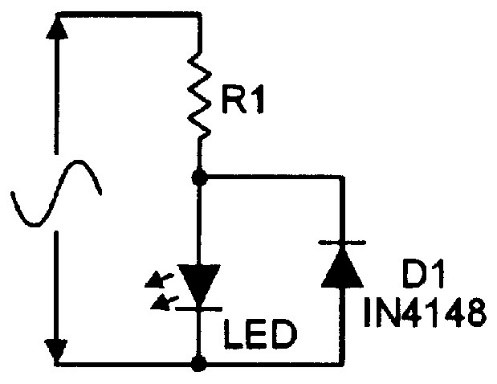
Below are 2 drawings, A and B. Drawing A is how the typical led replacements that you can buy installed inside of a bayonet or screw in style base. Very simple circuit right, a resistor of whatever value the manufacturer chooses and an LED diode. Only one problem, this circuit works just peachy keen if you are going to use it with DC power, or a battery. What we have found, is that the led’s in this circuit just do not last and are not very bright. Why? Because an LED is still just a diode. A strange one yes, but just a diode, and diodes do not like being powered by AC. Been there done that, and replaced for customers a whole bunch of the A circuit LED’s. We now use the circuit shown in design B. The resistor we use is a 1000 ohm resistor, which will give us a really bright LED. The addition of the 1n4148 diode creates a circuit when combined with the LED, makes a ½ wave bridge rectifier, which provides a very stable dc voltage across the LED. In the drawing you will also notice that the A circuit shows a dc power supply and the B circuit shows an AC power supply, which is what our transformers supply. The AC circuit is typical of the Christmas led light strings. What makes that work ok? The number of diodes in a row, provide the conversion to DC by themselves, which is fine, but a single one nope sorry.

I can’t get these darn O22 switches or controllers you sent me to work!!!
Ok, I believe you. We get at least 10 calls a year like this, and almost all of the issues are due to installation problems caused by:
- Incorrect wiring to the transformers
- Installing the accessory (new style bootstrap plugs) incorrectly.
- Insulating pins not correctly installed
- Using multiple transformers
- Issues created by using switches to go between multiple loops with separate center rail power sources.
We will address each of these bullets completely, but first I think it will be beneficial if we discussed just exactly how these things work. Please excuse the long winded nature of these, but don’t know how to do it any shorter.
What makes the switch change direction?
Remember as a kid when you made a magnet by wrapping some wire around a nail and attaching each end of the wire to a battery? What you did was create an electro magnet. Pretty powerful remember? Ok, so pretend you wound the wire around a paper tube, and put the nail so it would slide inside the tube. By doing this you then created a solenoid. If you then hooked up the battery to the wires, and put the nail on one end of the paper tube, the nail would either be sucked into the tube, or pushed away from the tube. If you changed the direction as to how you would the wires around the tube, for example instead of clockwise, you went counter/clockwise, you then would reverse the direction of push or pull on the nail. So……
In each switch there are 2 coils of wires wrapped around a paper tube in line with each other. One coil is wound clockwise, the other counter clockwise. There is a rod with a pin on one end that can slide back and forth in the paper tube. In the px below, the coil winding was not drawn correctly, At the center mounting point of the 2 coils is a wire from each of the coils. These 2 wires (one from each of the coils) are soldered together and goes to a power source. This power source is the pin that is located on the side of the plastic housing where the power plug pushes into. The switch works best if it has constant power not controlled by the same power you run your engines from. The other end of each wire goes to one of the outside screw down terminals on the switch motor assemblies labeled A and B
2 coils that move the rod inside the tube. The rod that moves the switch is attached to the mounting plate, which in turn has the pin attached to.
This plate that has dots around it is pushed or pulled depending on which end of the coils is grounded. Ground for example A and the plate moves left, Ground B terminal and the plate is pulled to the right. The plate has a pin riveted up in the plate, which goes thru the switch moving assembly, which changes direction. So when the plate is moved to the left, the switch moves to the curved position. When pulled it moves the switch to the straight position.
Next check out the drawing of the original remote control. You can see that all it does is provide a short between either the A terminal or B terminal (never both) to Ground which for is always the place where the outside rails are wired to. The center screw is internally wired to the outside rails. Our controllers work exactly the same except we get our ground connection from the transformer, where the outside rails are wired to, and use modern action switches and extra large LED’s.
The lantern light. The lantern light is always wired to the center rail power in the switch. It is not connected to the switching mechanism at all.
The moving switch plate outlined in dots, is only purpose to provide the circuit which lights the lamps on the remote control. It is also the source of many problems.
Sooo, now that we have that base covered, lets go to the problem area bullets
- Incorrect wiring to the transformers
All our controllers wiring to the transformers are exactly the same, and must be wired correctly. Here we will address what each wire does
Yellow wire: It is to be wired to a ground connection yes, but it must be the same ground that goes to the outside rails. This wire provides the ground to the controller which when the action switch is activated, sends a ground signal to one of the outside screw down terminals.
Red wire: This wire goes to a constant voltage source between 14 and 20 volts that does not change when you adjust train speeds. Some transformers have totally isolated power sources, which means you need to run separate ground wires instead of outside rail power. These power sources will NOT work. Here is how you can check this. On the accessory wiring point on the transformers, where you believe the red wire should go, attach a wire and then scratch the other end of the wire to an outside rail. If you get a spark you are good to go. If you do not, the controller will not work properly. This wire eventually goes to the red wire in the long cable which will send constant power to the switches.
Black Wire: This wire goes to whatever terminal on the transformer that you wire the center rail, where on your layout the center rail is wired to. It is shorted directly to the black wires coming out of the long cables. IMPORTANT NOTE: If your controller is for 2 different loops, each with their own center rail power source, do not use this wire, it will short both loops together! The purpose of this wire is to provide a center rail power tap. If you question this at all, just don’t hook it to the transformer. It is not necessary and has no function towards the switch operation, but can cause problems. Also if you use 2 separate transformers it is a good idea, not to use this wire. In the switch where the plug goes in this wire is attached to the white wire on the plug which powers the outside metal of the plug which is hooked to an internal strap inside the switch that goes directly to the center rail.
- Installing the accessory (new style bootstrap plugs) incorrectly.
RED WIRE: The red wire in the long cable needs to go to the red wire on the plug. This provides the constant power to make the switch work.
BLACK WIRE: This wire is attached to the outer part of the plug which inside the switch is connected to the center rail. It’s purpose is to provide a center rail power tap, so your trains do not slow down by themselves when running near the switch. It is totally not in any way a part of the switch operation, and can be not connected if you wish. If for example you are operating 2 different loops with separate center rail power sources, do not use this wire.
- Insulating pins not correctly installed: Check the above diagram and not where the switch rails are that are labeled control rails. IT is vital that these rails have insulated pins to insure the No D rail feature on the switches work properly. If your switch is being used to connect 2 separate loops together or to a spur line, you will need to install a center rail insulated pin on the center rail that goes to the spur track or other loop.
- Using multiple transformers: On very large layouts, it is often necessary to run multiple transformers. Understood. The idea of running a separate transformer to operate your switches, or remote control tracks, is a bad idea and totally unnecessary. The switches themselves only use power when they actually switch. They draw no power till then. The amount of power needed it operate the switch mechanisms is very little and lasts less than a second. The issues of different grounds, phasing issues way outweigh any proceed benefit you may have. On my layout a few years ago, I had 24 switches. I computed at the time that all the lights in the switches and remote controllers would draw almost 10 amps. With the changeover to LED’s the current draw went from 10 amps to less than ½ amp for all the switches combined. So again using separate transformers to run your switches is not only a bad idea, totally unnecessary with our advanced controllers.
- Issues created by using switches to go between multiple loops with separate center rail power sources: As previously mentioned, whichever leg of the switch will be going to another track loop or a spur line, you need to install a center rail insulator at that point.
Ok, there you have it. As always if you wish feel free to call/email/and or text me. You guys are fun to talk to and try to remember, this is supposed to be fun! Truthfully, the actual no of switch or controller failures we have genuinely had in the past 3 years is less than I have fingers.
In a typical o gauge layout which transformer lead is really the ground lead?
Great question. The answer? None of the leads coming from the transformer are a ground lead. All post and prewar transformers operate from AC power. Some of the newest stuff out there operate on DC which really do have a ground. But in the case of all the rest there are 2 identical power sources, with the exception as they are different only in phasing.
The picture below is a graphic picture of a typical ac voltage. From the point where the power is created, there are 2 wires attached as shown here. And here
The distance between the upper and lower peaks, determine the frequency of the signal, for example normal household voltage is 60 cycles per second or wavelength. The height of the two determine voltage. The reason they don’t short out is because they are 180 degrees out of “phase” which also explains why when using multiple transformers they have to be “in phase”.
In other words the bottom spikes must be in alignment with the other transformers bottom lines.
Or if you prefer, and just everybody else agrees whatever lead goes to the outside rails should be considered as the ground lead, which is just peachy keen with me.
You probably can’t make a mistake that we haven’t already made! Fortunately, we’ve learned from our mistakes, and in many cases, figured a better way to do things. Here are a few “Tech Tips” to help you in your quest to build The Perfect Layout and get those trains rolling again!
Phasing Transformers
If you’re running more than one transformer on your layout, they need to be phased properly, or they will short each other out. Fortunately, this is an easy job.
Your secondary transformer should have a place to install at least 2 wires. The larger transformers like the KW’s or ZW’s will have multiple “ground, or common” terminals that connect to the outside rails of the track. It is these terminals that we are concerned about.
The simple way: First plug all your transformers into a power strip. Then put a wire on whatever number of transformers you have on the common terminal of each transformer. Touch any two wires together, no big spark you are good to go, big spark, reverse the plug that goes into the wall. The spark should disappear. On your plugs put some kind of a mark on the plugs so you know they go in a certain direction on your power strip. What we do, is cut off the original plug and replace it with a 3 prong plug. Just don’t put any wires on the odd prong. then once you figure out which wire goes where, you will never have to worry about them again.
The truth about model train AC transformers
| We go thru latterly hundreds of transformers, and anything over 20 volts is highly unusual. You also need to realize these transformers are relatively crude devices. There are no regulatory circuits built into them. The power from the wall socket is hooked directly to the primary of the transformer, which means of course the output of the transformer will be in direct proportion to what the input voltage is coming out of the wall socket. I have seen variations as low as 108 volts and as high as 124 volts. That’s a variation of 12% which will equate to up to 2+/- volts on the output side of the transformer. Also FYI we have recently built some very sophisticated test equipment to give us accurate means of determining exactly what the various transformers will produce, not only in voltage, but in watts and amps. Telling someone that their transformer is great because it does 21 or more volts, is worthless, because it does not tell you what the transformer does once you put a load on it. With the equipment we have we can actually watch the voltage drop on every single transformer we see. How much it depends on how much of a load we put on the transformer which can be varied from O to up to and including 15 amps, which is way beyond any model train transformers capability. Sorry for the soapbox, but I grow weary with folks being misled by other people who either don’t know what they are talking about, or only want to tell you what they think you may want to hear.
What to hear some facts? Warning you may be a little disappointed. Theoretically if you purchase a transformer that is rated at for example 200 watts, it should produce enough current to hold a voltage of 20 volts for example with a 10 amp draw. (amps X Volts =watts) I guarantee you there is not a hobby transformer made that will do that. A laboratory AC power supply will of course absolutely do that, if you don’t mind spending 5 to 10 thousand dollars on one For example a typical ZW transformer no load voltage of 20 volts will drop to 16 volts with only a 3 amp resistive load, about what a single engine diesel will draw. Now in fairness, once the engine is moving along its merry way the current will drop and therefore the voltage will increase in proportion. IN short, 75 clean watts should drive a single train just fine. If you want to drive 4 trains, than you need 300. |
“cd” conversion for O27 switches
Most good quality O gauge remote control switches have a feature where if a train is heading into a switch the wrong way the switch will change directions automatically to accommodate the train so it won’t derail. This is a really cool feature but is lacking in most all O27 remote control switches. Why? I think it is more because the manufactures wanted to show more value to the O gauge stuff. That plus to do the job right there needs to be an electrical switch installed in switch to indicate on the remote control when the No D Rail feature is activated.
So anyway. Converting a old style O27 remote control switch to have a NO D Rail feature is quite simple. There is a tech tip on the site that will show you how to do it. Once you have done that, you will discover a problem associated with your conversion. When a train hits your NO D RAIL section on the switch or an external track, it does it job by activating a solenoid on the switch which is responsible for making the switch turn. When the train exits the switch the power is removed from the solenoid and the world is right again……except. While the train is going thru the switch the solenoid is fully powered, drawing juice, and often will make an irritating buzzing sound. And if you happen to park your train on the NO D RAIL switching the power will again be sent to the solenoid constantly. Eventually the switch mechanism will heat up to the point where it can self-destruct. That issue becomes worse if you have modified the switch as we do for all of our O27 switches to operate from high power accessory voltage. If you use normal center rail power to run the switch, the current draw will also slow down the train, and the more it heats up, the slower the train will go.
The solution….
If your switches are not set up for constant accessory power to make the switch work, that needs to be done. Not just for this purpose, but they just work a lot better than trying to run them on center rail power. On some switches like the hump backs or the 1122’s that chore is pretty tricky. There are lots of articles on the web as to how to do it. We here at TinMan, make those modifications on all the switches we sell that do not have it before we sell the switches. We also have a service to modify your switches if you like. FYI there are some switches, for example all the Marx switches that are already set up for accessory power, as well as some of the K lines. Virtually all the remote switches we sell today either are set up for accessory power, or we have modified them to do so. However once we have done that we have the problem of over heating etc.
The solution! A really smart guy “Rob Nelson” came up with an idea of adding a cd circuit to the accessory power that operated the switches. How it worked was the switches were actually operated by a capacitor discharging. If a car was parked on the No D Rail track the capacitor would not recharge, and therefore would not damage the switch. Once the car was removed, the capacitor would recharge in a matter of seconds, and was ready once again to operate the switch again. Not bad eh? We were so impressed by all all this creativity, we now include accessory power and NO D Rail capability with all the O27 switches we offer. In addition we now include the CD system in all of our “red button” controllers, at no extra charge. We just cannot take credit for the invention so we have named these controllers the “Bob Nelson Controllers” Just our way of recognizing a really smart guy, who willingly shared his invention to anyone who was interested. If you are still around Bob, our sincere thanks to you.
How convinced are we with this new system? We now include the Rob Nelson CD system with all our red button controllers, including with switches that include the red button controller.
How its done:
The system is really quite simple. It is comprised of 3 electrical components. Which are:
- A diode which converts the AC voltage from the accessory power to the switch to DC
- A resistor, which goes in series with the diode.
- A large capacitor which then goes in series with the diode, and is also hooked up to the switches solenoids. (the solenoids is what actually makes the switches turn direction).
How it works, is the AC voltage is converted to DC voltage and then goes thru the resistor and diode and charges the capacitor. What is a capacitor? For this discussion it is like a rechargeable battery, except once turned on it drains down to nothing in a matter of a fraction of a second. It then stays dead until it can be recharged again. The discharging of the capacitor operates the switch mechanism. The resistor in series prevents the recharging until the ground connection from either the controller or the NO D Rail system is removed. Once the ground connection is removed the capacitor recharges in a matter of a second or two and is ready to operate the switch again. In the meantime, while being energized, once it has operated the switch it draws almost no current from the transformer, stopping the buzzing and the issue of potential over heating of the switch. Pretty cool eh?
The TinMan/Rob Nelson system:
We now add the CD parts into our O27 switch controllers for all our switches that have been modified for accessory power. No wiring changes need be made by the customer. Because our controllers can operate 2 switches at once, we had to add some extra components to the design, and it works super well. It actually improves the action of the switches, and they switch a lot faster with the CD system than they do without. They work best with an accessory power input of at least 14 volts. We include these mods to all the controllers that will be used with our modified switches, and we offer a new “CD” controller for those who have switches that were already modified.
So there you have it, now you are an expert in CD systems for model railroad O27 switches!
What’s the scoop about the “cd” conversion for O27 switches?
It all started here……..
Most good quality O gauge remote control switches have a feature where if a train is heading into a switch the wrong way the switch will change directions automatically to accommodate the train so it won’t derail. This is a really cool feature but is lacking in most all O27 remote control switches. Why? I think it is more because the manufactures wanted to show more value to the O gauge stuff.
So anyway. Converting a old style O27 remote control switch to have a NO D Rail feature is quite simple. There is a tech tip on the site that will show you how to do it. Once you have done that, you will discover a problem associated with your conversion. When a train hits your NO D RAIL section on the switch or an external track, it does it job by activating a solenoid on the switch which is responsible for making the switch turn. When the train exits the switch the power is removed from the solenoid and the world is right again……except. While the train is going thru the switch the solenoid is fully powered, drawing juice, and often will make an irritating buzzing sound. And if you happen to park your train on the NO D RAIL switching the power will again be sent to the solenoid constantly. Eventually the switch mechanism will heat up to the point where it can self-destruct. If you use normal center rail power to run the switch, the current draw will also slow down the train, and the more it heats up, the slower the train will go.
The solution….
Step one:
If your switches are not set up for constant accessory power to make the switch work, that needs to be done. Not just for this purpose, but they just work a lot better than trying to run them on center rail power. On some switches like the hump backs or the 1122’s that chore is pretty tricky. There are lots of articles on the web as to how to do it. We here at TinMan, make those modifications on all the switches we sell that do not have it before we sell the switches. We also have a service to modify your switches if you like. FYI there are some switches, for example all the Marx switches that are already set up for accessory power, as well as some of the K lines.
Step two:
Once you have your switch modified for accessory power you can add the “CD” system to the power that goes to the switch. This idea originally came from a really smart guy that participates in some of the O gauge train forums. Sorry, but I cannot remember his name. His system was to add a few electronic components to be installed between the transformer and the switch. These parts consisted of a large capacitor, a diode, to convert the transformer AC voltage to DC and then charge the capacitor. A resistor needs to be put in between the diode and capacitor. How it worked, is the AC voltage is converted to DC voltage and then charges the capacitor. What is a capacitor? For this discussion it is like a rechargeable battery, except once turned on it drains down to nothing in a matter of a fraction of a second. It then stays dead until it can be recharged again. For our purposes, the discharging of the capacitor operates the switch mechanism. The resistor in series prevents the recharging until the ground connection from either the controller or the NO D Rail system is removed. Once the ground connection is removed the capacitor recharges in a matter of a second or two and is ready to operate the switch again. In the meantime, while being energized, once it has operated the switch it draws almost no current from the transformer, stopping the buzzing and the issue of potential over heating of the switch. Pretty cool eh?
The TinMan system:
We now add the CD parts into our O27 switch controllers for all our switches that have been modified for accessory power. No wiring changes need be made by the customer. Because our controllers can operate 2 switches at once, we had to add some extra components to the design, and it works super well. It actually improves the action of the switches, and they switch a lot faster with the CD system than they do without. They work best with an accessory power input of at least 14 volts. We include these mods to all the controllers that will be used with our modified switches, and we offer a new “CD” controller for those who have switches that were already modified.
So there you have it, now you are an expert in CD systems for model railroad switches!
Making your own insulated track sections
As many of you know, insulated track sections are a very popular item to your layouts. They are used for a lot of different purposes, including activating some of those great toys, like the little man who comes out of his house with a lantern when a train goes by, and operating crossing gates, dwarf signals, controlling spur powers to name just a few. We at TinMan3rail have been building these track pieces for quite some time, and have like you struggled to find a proper insulating paper to use. This single item has made the process of making insulated track sections a real pain in the……. Lionel originally used a very heavy paper that was originally designed to be used as an electrical insulating paper. See, there was no nylon, or plastic materials available back then, so someone came up with the idea of designing a very heavy paper material to use as a very good electrical insulator. Somewhere down the road, it was nicknamed “fish paper”. Someone said that this heavy duty paper was used to wrap fish that was purchased, from the “fish shops” The color of paper is a dark grey on one side, and a light grey on the other. Soooo now that we finally have come up with a procedure for making insulated track sections that works very well. So from us to you, here is how to do it!
The first step is to remove the outside rail from the track ties. Our method is to use our track pliers. We grap the rail on the top of each tie as shown below and bend the rail over. The rail will then bend the tabs and pop out and away from the tie. Do this for all three ties, and the rail will fall away from the ties. The next step is to bend the tabs that hold the rail down vertical as shown in the third px.


Now the rail is separated from the ties and the tabs on the ties should all be vertical. As shown below:

Now the rail is separated from the ties and the tabs on the ties should all be vertical. As shown below:

You then place 3 insulators in the widened tabs of each tie. You then place the rail back on the track in its original position but now will have the fish paper between the rail and the ties. The you need to slightly bend the tabs together so they start to bend around the base of the rail. Next take your tie protector chunk, and put it under a tie, like shown


Turn the track right side up and use our special tie spike tool, to tighten the tabs around the rails, add your insulating pins, and a wire to the insulated rail, and Walla, you are done! You now have an insulated track section:

Repairing Lionel O22 Switches
We at TinMan repair and refurbish hundreds of switches a season. We are normally not bashful about sharing the tricks of the trade that we utilize. However we have found there are no real easy repairs to these switches, especially the O22 variety.
When we first started out with this project we were sponges trying to learn all we could from the “experts”. We very frequently discovered that in many cases there were different opinions regarding what to do or not to do with these switches. Opinions on lubricants were always a hot topic of contention, some fellows think that the right snake oil is a magic answer, others say no to any kind of oils etc. We experimented with new electronic solutions to the problems with the slide switches, but found them uneconomical and very complex.
Well after several thousand switches, here is what we came up with. These switches are quite complex devices with elements of, mechanical parts, Electronic parts, wire issues, contact issues, lantern and Lantern holderoners ( a switch repair guys technical term) , contact points, screw terminals, solenoid coils, poor factory soldering of connections, etc.
What we discovered thru all this is there are no magic simple answers. A little too much bend here, not enough there, the old style solder that causes conductivity issues, wires that the insulation is partially worn out, working with bimetal issues, and the hits just keep on coming.
Yes sure a lot of switches can be cleaned and processed very quickly. But 50% or more we see require a lot of work to get them back to original manufactured performance levels. We find there is no substitute for thousands of dollars worth of electronic as well as mechanical tools are necessary to be serious in this business.
Granted many of the switches we get have not worked for years, and are in really bad shape. The worst of them is always when someone with all good intentions tried to repair, then gave up. The first thing we then have to do, is undo someone else’s’ fixings. For example we use very sophisticated variable short circuit proof power supplies, that not only monitor voltage but also current.
We can tell more about how a switch is working by watching current and wattage that the switches draw than any personal observations. As much as we love these kinds of toys, this is still a business, and spending thousands of dollars on test equipment is not fun.
Bottom line? I would not be doing you any favors trying to tell you how to fix these switches properly, there are just too many interconnecting things that effect performance. And, to make matters worse, we are routinely discovering new issues that require yet again more creativity to take care of. So many times you discover a problem and repair it only to find out that you now opened up another can of worms.
Anyway, that is why we have decided not to try to pursue this portion of the business in our web site. We recondition switches for about $20 each and includes all new LED’s, changing all cables, and guaranteeing them for a year. I understand that a lot of folks just enjoy putzing, and we certainly understand that, but the facts are, when we ultimately get those switches and have to spend a large amount of time undoing what others have done…..Oh well.
BEFORE YOU SCREW DOWN YOUR PLYWOOD!
First a word to the wise, you will be spending a lot of time under that table, adjust the height where you are comfortable sitting on the floor, and still work on the wires in relative comfort. Table too high, too much stretching, too low, hits your head.
As we all know the underside of our tables very quickly can look like a spaghetti bowl of wires going to who knows where. Here are a few tricks we have learned over the years.
First another investment. Pick up a 1″ Irwin speedbor drill bit. like below:

They are around $7 at Lowes. You can use your cordless drill with this guy, but be careful they drill really quick and will grab if you don’t go in straight. Do not push, let the drill do the work. Anyway in your framing (usually 1X3’s or so) that goes under your plywood, drill a hole every 18″ or so, and then when you string your wires thru and keep them from drooping all over.
Then: figure where your transformer(s) will be. What we did on our 12’X24′ layout was, we bought a roll of 14 gauge 3 wire romax. As you know this wire will be covered with white plastic insulator. We then stripped off all the outer insulator wire except left a few inches around the cable every couple of feet to keep it neat. The 3 wire Romax will actually give you 4 wires. One red, one black, one white, and one non-insulated which can be used as a ground. After doing the prep work, we then made a loop of the wire thru the drilled holes, all the way around the table.
On our layout we actually used 2 runs of the Romax so we could have 4 wires for separate train loops, one wire for accessory power the unshielded, wire is used for grounds, another for a bumper car and another for trolleys. To splice into the wires we use another Irwin tool. This is a $20 tool, but well worth it. I would stay away from the cheap imitations, we have enough aggravation in our lives, why invite more. I believe Lowes sells this tool also.
This stripper is really ideal for us guys because you can easily put it anywhere on a wire and strip off the insulation, making splicing into the wire a breeze. Remember when doing that, always do your splicing at different locations on the wire, so they cannot possibly short out. you really don’t even need to add insulators, but if you wish, the easy way is to squish a piece of wire in the Romax into a very tight loop. You can then add your splice in wire you wish and use a plastic wire nut to tie the works together.
EASY REPAIR FOR BENT LANTERN HOLDERS ON O22 STYLE SWITCHES
We at TinMan recondition hundreds of switches and of course run across every conservable issue with the Lionel switches. One of the more odd ones is where a switch will not operate properly because the lantern hits up against the plastic housing and jams up the works. Why? Because the metal (some are plastic but issue is very rare) bracket that holds the lantern is bent so it will not allow the lantern to turn evenly in its place.
Solution is simple right? Somehow the holder got bent, possibly from the switch being dropped or who knows. Worked once right? No problem, get out the trusty slip joint pliers and bend it back. Absolutely guaranteed, every time we have tried to do that the holder snaps off. Now we have a really fun job of replacing the holder with a new one.
How is that possible that it breaks that way? It bent once without breaking, why not a second time. Have no idea, just know that is what will happen. Yeah I heard that guy from New York, saying, yup, been there done that, or maybe it was Maine? Oh well.
THE FIX!!!
We use one of those cheap Harbor freight mini torches and heat the bracket up right where it meets the base, and the holder can be bent up very easily. You can even use one of those Bar B Que lighters if you like. I remove the heat source and bend it straight with a medium slip joint pliers. . If you have a soldered in LED for the lamp, put a chisel or something between the lantern holder and light socket to act as a heat shield. I wouldn’t use a full size propane torches, they are too hot and can destroy your switch, or at least the wiring.
If you do elect to get one of those mini torches, a word to the wise. Buy Ronsen propane tanks to fill your torch. Every Walgreens sells them for a few bucks, and one can has lasted us a couple of years at TinMan. When you refill it, only fill it part way, the rest will probably leak out on its own.
How to convert your switches to add the auto non-derail feature
Most all O27 switches and even some of the O gauge switches do not have the auto non-derail feature. It is really a very simple modification that would cost pennies during the manufacturing process. So why did they not do it? Simple answer, to add value to the more expensive switches of course. So let’s see if we can beat them at their own game!
To start we need to understand what makes the switches change directions from straight to curve and vice versa.
Almost all remote control switches have 2 solenoid coils in them. A solenoid is nothing more than a whole bunch of usually very thin wire wrapped around a hollow core that a metal rod can slide back and forth on. Remember as a kid we used to take a nail, wrap a bunch of wire around it and hook up a battery to the 2 ends of the wire? </p>
Made a heckova strong magnet. Same principle with our switches, except as said the wire is wrapped around a hollow tube, and the nail is then allowed to move inside the tube. Wind the wires around the tube in one direction, and the nail will move for example from left to right. Reverse the direction of the windings, and the nail will move right to left. Attach the nail to part of the switch that moves, and wala, that’s how it works.
In actuality, most all the coils in the switches are wired so that one end of each coil is hooked up to a positive terminal on the transformer, or in some cases to the center rail of the track. The other ends of the coils are usually either attached to a screw down wire connection or to a post that has a nut you can tighten around a piece of wire.
One post to make the switch curve the other to make it go straight. At the remote control when you operate the pushbutton, lever or whatever, it hooks that loose end of the coil in the switch to ground thru a wire between the remote control and the switch, which turns on the coil which makes the magnet that either pushes or pulls the rod that moves the switch.
With the more expensive switches, a ground connection is made by insulating one of the outside rails right on the switch, so that when the wheels of the train hit that insulated piece of rail, a connection is made to ground by shorting out the insulated section with the axel that the wheels are mounted.
The problem with the cheaper switches especially O27 they are put together with rivets and sometimes very difficult to take apart and work on. Or the switch housing is all metal and not designed to handle an insulator. So here is how we beat the system.
The very first track section that goes into the switch ends that either goes straight or curved, you remove one of the outside rails and install insulator pins in place of the steel pins. The you will need to add rail insulators to one of the outside rails. Just like the center rail is insulated.
Then either solder or slip a piece of wire on the bottom of the rails by prying the point where the rail comes together and put a piece of wire there, and attach that wire to the appropriate screw or post terminal, or use a lock-on and tis done! I like using 1/2 straights or curves for this purpose, but almost any track section will work, even if it is only a couple of inches long.
Elsewhere on this site are detailed instructions on how to make your own insulated track sections.
Gilbert American flyer switches wiring
Most American Flyer switches have 4 wiring posts vs. 3. Some people thought that is because they had a auto non-derailer feature.. Sorry, not so.
First a brief description as to how most all switches work.
Most all remote control switches work by using a pair of solonoid coils. One coil pushes and the other pulls. They accomplish this by reversing the way they are wound on the spindles. One is wired clockwise, the other counterclockwise. Both coils are normally hooked up so the turns closest to the center of the 2 coils are wired together to form a common power point.
Then there are two separate ends of each coil that are usually grounded to activate one of the coils so the effect is the coil either pushes or pulls a rod which is attached to the portion of the switch that moves the rails. For example activate the push coil and the switch goes to the turn out position. Activate the pull coil and the switch moves to the straight position.
This electrically is accomplished by what is technically called a double pole single throw center off switch. Normally the switch is in the center position that does nothing. When you push the switch lever up for example it may activate the push circuit, down the pull. If you are thinking that would only require 3 wires you are right. So why does our American flyer have 4? Heres why:
Black Post: This post is normally attached to the accessory positive terminal on the transformer. Inside the switch the power is hooked up to the center connection of the two coils and interestingly enough the screw part of the light socket.
Yellow Post: This is hooked to the center terminal on the light socket. It would normally be hooked to ground.
Green and Red posts: These two posts are hooked up to the outside wires of the coils. When you ground one of these posts, the solenoid is activated and will either push or pull the switch
Can you modify this switch to operate like the Lionels’ and some of the K Lines’ where they will auto change to prevent derailleur’s? The only way I can figure would be to use one of those weight sensing switches where when a train runs over the track with the weight sensing switch under it , it would send a ground signal to the appropriate screw terminal. That should work ok.
UPGRADE CONVERSION FOR LIONEL SWITCH CONTROLLER
The technical prowess shown by the original Lionel team was amazing considering what they had to work with in the early part of the 20th century, however some things older is not necessarily better. One for sure is the original rubber wire cable that came with the O22 and other switches. 1st unless you were building a midget layout, the cable is way too short. Next after just a few years the cable becomes brittle and eventually is unusable. If you run bootstrap power you will need a separate cable for that. Then if I want to run power taps for the track, another cable. Sooo, if I have to run a cable to control the switch, why not have it do a lot more? This conversion will also provide constant switch bootstrap power, an additional power tap for the center rail of the track, and all normal switch and remote control functions The only parts you will need are:
15 feet or so of 4 conductor cable. A 2.5mm power plug, to replace the boot strap, soldering iron, some solder and about 10 minutes of your time. If you wish a kit will be available soon from TinMan3rail.com for about 10 bucks with shipping, and includes the wire, 2.5 mm plug, with wires soldered on, and 15′ of cable. If you need more than the 15′ cable, or 3′ to the transformer, let us know and we will extend it for you to your specs
This cable is to be wired to the transformer. This cable is to be wired to the switch.

The transformer cable is about 3′ long and is stripped of the insulation at the 3′ mark about 3″ worth.
The red and black wire go all the way from the transformer cable thru the longer right cable untouched.
The green wire is pulled out of the 4′ piece of cable, and wired to the solder terminal next to the green light . The white wire is cut 1/2 between the 2 rolls of cable. The white wire that is part of the transformer cable is wired to the switch solder lug. The white wire from the long cable is soldered to the red light bulb solder lug.</p>
The end of the 3′ cable:
The red wire goes to accessory power that you would normally run to the boot strap.
The black wire goes to the track power terminal that is connected to the center rail of the track the switch is hooked to.
The white wire is hooked to the common terminal on the transformer. </br>
The long cable
The red wire will go to the center terminal of the 2.5mm plug.
The black wire will go to the outside (barrel) connection of the 2.5mm plug.
The 2.5 mm plug will go directly into the 022 switches. For some of the newer switches, you need to use a 2.1mm.
The green wire goes to the right screw down terminal on the switch assembly.
The white wire goes to the left screw down terminal on the switch assembly (if your switch works backwards reverse the green and white wires).
The center terminal of the switch is not used. Originally it provided a ground to the remote control switch, which is now being provided directly from the transformer.
Trouble shooting uncoupler and unloader tracks

The only difference between the O27 variety is that the wires are soldered directly to the track parts that are shown above, and the O27 version does not have double accessory rails.
The yellow wire goes to ground or screw no 1.
The blue wire goes to screw no 4
When you push the unload button, it creates a short between pins 1 and 4
When you push the uncouple button (the orange one or the big one we installed on the controller, it sends accessory voltage (the red wire in the short cable that goes to the transformer accessory power) directly to the uncoupler coil.
The black wire in the short cable is hooked to normal center rail train power and is used to provide a power tap to the center rails of both tracks.
Troubleshooting procedures:
Using a continuity tester (or an ohmmeter)
1. Attach one lead to the short cable red lead. The other lead to the outside rails of the unloader track. Operate the uncouple switches. It should show short to ground when you operate the switch, because it will read thru the uncouple coil. It should be open when not switched. </br>
2. Repeat above for both the unloader rails on the unloader track. It would be better if you unsoldered the neg lead of the coil on the dual track so you will only be checking the accessory rails, and not thru the coil.
I doubt there are any issues with the switch wiring. The rate of failure on these is so high that when we begin the process, we thoroughly check every switch and over 50% of the time have to adjust switch contacts, or use an emery cloth to clean them. We then double check the switch actions after completing our wiring to them. I suspect the error will be in the wiring to the track (happened before)
If you have trouble, set yourself up a little test bench and give me a call 262-914-0057 and we can work together to solve. Should be fun.
Rich…..AKA TinMan
How to install those spade connectors on very small wires:
Yeah I know the wires are small but they work and keep the cost down. But I have seen some folks have a problem crimping on the spade connectors. Here is a trick we use that works pretty good.
Step no 1 Spin the stripped end with two fingers to make a tight braid as shown below:

Then fold the stripped end over the outside plastic insulator thus:

Then slip the spade terminal over both the wire and insulator and crimp. Make sure it goes in far enough so you are also crimping the insulation portion. The picture above is a little long on its fold over.
It is important that if you are using a crimp tool as shown that the pointed end goes over the part of the connector that is NOT split as shown.

If all went well, when you are done, it should look like this, and unless you are mighty mouse, you will not be able to pull them apart.

Soldering
What you will need: Buy a good old fashioned soldering Iron. A great one to use is the original Weller 100 watt (w100p) iron that is available anywhere they sell hobby supplies for stained glass. Prefer the model that comes with a 2 prong plug, because the tip is not grounded. Very important for working on stuff that may be powered up. If the one you buy has a 3 prong plug, do the unforgiveable sin and cut off the round prong off the plug.

These Irons are also available on line from companies like Zoro and sell for about $70. May seem like a lot, but last a lifetime, and are not hurt to leave on for days on end. The tip it comes with is about 3/8″ wide and perfect for soldering wires on the bottoms or sides of tracks. For finer work, you may wish to buy the 1/4 or even 1/8″ tip for this iron. Solder: for anything electrical, buy rosin core solder, 60/40 works best. We like the 062 size.
For soldering tracks together, use acid core solder (same stuff they sell for soldering copper water pipes). Do not use this solder for electrical soldering, Can use the same soldering iron and tips, just wipe off the old solder on a wet sponge. A good pair of needle nose pliers. We prefer the larger 8″ heavier style for train work like this one made by Stanley. they are also great for sizing track ends etc. About 10 bucks.

Heat is your best friend, or worst enemy. The work you are going to solder needs to be hot enough to melt solder, but not so hot as to damage anything. For track power wiring, practice a few times on the bottom of a junk piece of track. Procedure:
Scratch off any grease, oil, dirt etc till you see raw metal. A pocket knife works fine. Tinplating is ok. Hold your iron firmly on the place you want to solder a wire. After about 15 seconds or so, take your solder, initially melt on the tip of the iron, then flow onto the track. Pull back the iron. Strip your wire you want to use, between two fingers, spin the wires together (assuming the wire is stranded). Always cut a little shorter than you think you will need.
The heat of the iron will always melt back some of the insulation. Coat your wire with a little solder, the same as you did with the track, (called tinning). Then put the wire on the cold solder you put on the track, holding the wire with a needle nose, heat the wire, till the tinning melts, and flows into the solder you put on the track. Keep holding the wire in place with the needle nose, and remove the iron. If you did good, a strong tug will not remove the wire from the track, and no excess wire threads will be seen.
To-Lock on or To Solder
Big topic of debate. Which is better? Well the tech in me will always say a soldered connection is always the best. The realist in me says yeah but the lock-ons will also work. The negative of the lock-ons is they are ugly and the wires can get tangled up in the trains.
So if we are going to be brave and do the soldering choice then……Please do it right!
In order to get a good solder connection you must remove any dirt, grime, galvanizing, or other foreign materials from the track. Please do not solder the sides of the tracks. Solder your wires on the bottom of the track away from any ties. Use at least 20 gauge wire (just enough to get thru the board and leave 6″ or so working room left).
You will notice that the px below shows where we had to clean the bottom of the track. Not shown is that we also apply some black hot glue over the solder joints to protect the area from rusting, and act as a strain relief. Usually if you are adding wires for a power tap it is usually not necessary to add a wire on the outside rails. This is only because there are twice as many connection points on the outside rails.

How to convert your non Lionel O22 style switches to have the non-derailing feature
This cute little trick will work with virtually any remote controlled switch. including all Lionel, Marx, American Flyer, Marx, and K line.
Check out the tech tip titled “make your own insulated track section”
First a trip to harbor freight is in order for the following: This little guy lists for a grand total of $15 and is an indispensible tool for working with trains. We use it to clean the bottom of tracks to make good solder connections, and when we have to cut a piece of track it makes a very quick clean cut. We use this tool so much we clamped it into one of our vice’s. Then we can feed the work into it like a table saw. Works good, just don’t tell Osha! You will then need some metal cutting wheels, about $10 for a pack of 10 or so.

Ok so here we go, take a piece of track and cut one of the outside rails between 2 ties you only need a section of track not more than 1″ long. Then remove the short piece of track, following the instructions in “make your own insulated track section”. You will need to put an insulator wire or clip between the places where you cut the track and the other end of the piece you cut.
The wire that is attached to the track to the remote control screw terminal that is responsible for changing the switch direction that yours, need. Remember you will need to make up 2 tracks, one for each side of the switch.
Make your own insulated track section
As our layouts become more and more complex we need ways to turn things on and off from our trains running past a certain point. Lionel originally made some gravity operated switches that were ok way back then, but as our trains became more and more complex, the weight of our engines changed, to the point where it is difficult to have them work thru the whole train cycle. The solution is to have a piece of track where one of the outside rails is “insulated” from both the rail ties, and the tracks on either side of the desired track. Lionel manufactured such a track but is no longer available and is quite expensive. Soooo here is a way you can easily make your own.
Stuff you will need:
a chunk of 1/8″ or 1/16″ automotive gasket material.
some insulting pins or check our tip on how to make your own.
Either some solder to solder the switch wire unto the rail or
Cut out 3 strips out of the insulating material about 1/2″ wide and 3/4″ long.
Take your track pliers and put on the rail over a tie. Wiggle the rail back and forth until the rail is nice and loose, repeat for all 3 ties.
You then should be able to bend the rail to the outside slightly and remove it from the ties. If you are a perfectionist, cut about 1/4″ off one end of the rail you removed. This will allow a little extra clearance between the tracks and the insulated one.
Spread the tabs so they are straight up and down on all three ties.
take your gasket material, and place it centered on the bottom of the rail you removed. Then take a heavy duty needle nose pliers and squish (that technical term again) the gasket material so it fits into the flat part of the bottom of the rail.
Put the formed gasket material on the rails over the ties and push the rail down on the ties. Make sure it is centered nicely. Use your heavy duty needle nose to squish the tabs on the ties around the rail. If you have one of our tie tools, tighten up the rail slightly to complete the job.
If you don’t want to solder then take a chunk of stranded wire (20 gauge is good enough) and strip off an inch or so. Take a knife blade and open the bottom of the rail just enough to slip your wire between the 2 pieces. and you are done. If you like us would rather solder, be sure to scrape off any tinplate or grime before soldering the wire to the rail.
Below are a couple of px as to what your insulated track sections should look like. Note the pin which is a piece of no 14 romax wire.


KW Transformer tech tip

This poor transformer has received more criticism than any other transformer Lionel ever made.
It really is not a bad transformer, its just the design engineers in my opinion got a little too cute, and the owner’s manual frankly sucks. So a picture is worth…….So let’s try to take the mystery out of this poor neglected step child.
First, these two terminals are shorted together inside the transformer and need to be hooked up to the outside rails on your layout.

These two terminals are used to run the trains and should be hooked up to the center rail for 2 separate trains.
This terminal should be wired for accessory power to for example switches, uncoupler tracks etc.It will give you a constant 19 volts or so no matter where your speed control is set.

These next two 14V have to be used together because they do not share anything with the outside rails. They are usefull for village lights etc. but you need to remember you will have to run 2 wires to each light. In other words for your lights one side of the bulb goes to the c terminal the other to the d terminal .
Lastly the C terminal that is supposed to wired like c and d (which gives you 14 volts) here you can use the outside rail power tap (u) and C to get 6 volts. For what have no idea, would have been a lot better if it would give 14 volts between C and U but no luck.
Other than that it really is not to bad.
So a summary:
U terminals go to the outside rails, no matter which one. they are both shorted together
A terminal is to run a train controlled from the A control lever and needs to be hooked to the center rail of your “A” train.
B terminal is to run another train and needs to be connected to the center rail for that train, again is controlled by the B lever
D can be used to operate all your switches, remote control uncouple/unloader tracks etc.
C and D hook to light bulbs